Immersive audio basics: formats, arrays, and spatial cues
Channel count alone does not create immersion. Recording must preserve direction, distance, and room reflections, and playback must reproduce those cues coherently.

Contents
What this article covers
6 chapters · About 8 minutes
Definition
Channels around the listener do not guarantee spatial impression
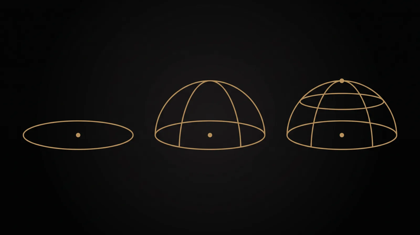
Industry writing often uses “immersion” and “envelopment” interchangeably. Here, immersion means the listener’s engagement with the complete sound field, while envelopment means spatial cues from the sides, rear, height, and room reflections. Sending the same mono signal to many loudspeakers adds source locations but does not necessarily form a stable spatial impression.[1] For loudspeaker playback, the height layer is the main distinction between three-dimensional layouts such as 7.1.4 or 9.1.4 and conventional 5.1 horizontal surround; binaural rendering can also present height cues over headphones.[2][5]
Formats
Read the layout notation first
5.1 contains five main channels and one LFE channel. In Dolby’s 7.1.4 notation, the first number counts ear-level channels, the second counts LFE channels, and the final number counts height channels.[3] ITU-R BS.2051 defines 22.2 as 22 main channels plus 2 LFE channels, with the main channels distributed across upper, middle, and lower layers.[2] “.1” describes an LFE signal channel; it does not mean the venue can use only one subwoofer. A format sets delivery and monitoring boundaries, while the recording array must still suit the sources, room, and spatial cues you want to preserve.
Ambisonics
Ambisonics is a sound-field representation, not a spherical microphone model
Ambisonics represents a sound field with spherical harmonics and is not tied to one hardware design. A common first-order microphone uses four nearly coincident capsules in a tetrahedral arrangement to capture A-format, then converts those signals into the W, X, Y, and Z channels of B-format. That is only one way to produce first-order signals.[4] Three-dimensional Nth-order Ambisonics requires (N+1)² spherical-harmonic signals. Higher orders usually increase spatial resolution and enlarge the useful playback area, but results still depend on frequency, decoder, and loudspeaker layout.[4][5] Delivery to 5.1, 7.1.4, or headphones always requires rendering for the target system.
Spaced Array
The 2L spaced array is a case study, not a universal template
Spaced arrays use arrival-time and correlation differences between microphones to capture spatial impression. DPA has described Morten Lindberg’s 7+4 omnidirectional array and stated that its microphones were at least about 1 m apart; in another interview, Lindberg explains that he changes the array for each ensemble and venue, with dimensions ranging from roughly 40 cm to 150 cm.[1][6] The sources describe different configurations, which is exactly why “7+4” should not be copied as a fixed coordinate set. Study the direct routing and relationship between lower and upper layers, then size the array for your own programme material.
Decorrelation
Decorrelation can diffuse the field, but it leaves processing traces
Decorrelation is not simply copying one track to more channels. Common methods use all-pass filters, time-varying filters, or short delays to reduce inter-channel correlation while trying to preserve spectrum and transients. It can synthesize diffuse sound and, in some reinforcement systems, reduce low-frequency variation caused by multiple sources.[7] Excessive processing can smear transients, alter timbre, or broaden localization. After processing, check correlation, mono compatibility, downmixes, and several listening positions instead of judging width only at the sweet spot.
Approach
Set priorities before choosing the array
When precise localization and post-production rotation matter, begin with a coincident or near-coincident approach. When hall envelopment matters more, consider a spaced array. Pressure omnidirectional microphones usually extend well at low frequencies, but they also capture more room sound and low-frequency noise.[1] The final plan must account for array size, reverberation, monitoring layout, and delivery format together. Routing each microphone directly to one loudspeaker channel is a valid method for some productions, not a rule for every immersive recording.
References
Sources
Standards, technical documents, and official manufacturer pages checked for this revision.
- 1Introduction to Immersive Audio: The Basics
DPA Microphones · Accessed 2026-08-09
- 2Recommendation ITU-R BS.2051-3: Advanced sound system for programme production
International Telecommunication Union · Accessed 2026-08-09
- 37.1.4 Dolby Atmos-enabled Speaker Setup Guide
Dolby · Accessed 2026-08-09
- 4EigenStudio User Manual
mh acoustics · Accessed 2026-08-09
- 5Scene-Based Audio and Higher Order Ambisonics: A Technology Overview
European Broadcasting Union · Accessed 2026-08-09
- 6Morten Lindberg: Immersive Music Recording
Sound On Sound / 2L · Accessed 2026-08-09
- 7Signal Decorrelation for Sound Reinforcement Systems
Audio Engineering Society · Accessed 2026-08-09
Related Products · Related products